MRS System and Simulation
This page will guide you through a simulation example using the MRS system.
Introduction
The MRS system is the entry point for all simulations as well as the deployment of autonomous features on our drones. Most of the information can be found in the official documentation as well as on GitHub.
In the following sections, we will cover the installation of the system, its architecture, and then we will focus on one simulation scenario that will get you prepared for your first autonomous flight with your drone.
Installation
The MRS system can run natively on Linux 20.04 but can also run on any other Linux distribution or Windows 10/11 using Apptainer. If you need to install Apptainer, please refer to this page. In the following, we consider the native installation.
-
Install the Robot Operating System (Noetic):
curl https://ctu-mrs.github.io/ppa-stable/add_ros_ppa.sh | bash
sudo apt install ros-noetic-desktop-full -
Configure your ROS environment according to ROS Tutorials
-
Add the stable PPA for libraries enabling autonomous system:
curl https://ctu-mrs.github.io/ppa-stable/add_ppa.sh | bash -
Install the MRS UAV System:
sudo apt install ros-noetic-mrs-uav-system-full
Architecture
As you can see from the GitHub page, the MRS system can be seen as a collection of packages that consist of different layers. Each layer serves a different purpose that we will briefly detail here.
-
MRS UAV CORE: It is a metapackage that handles core functionalities of the drone. It includes several packages dedicated to routines, algorithms, plugins, messages, and so on. One major package included in the core is the MRS UAV HW API.
-
MRS UAV HW API: This package consists of an abstraction layer between the MRS UAV System and the UAV Flight Controller. In other words, this package provides a unified ROS interface for the core as if it was a generic flight controller.
-
MRS UAV PX4 API Plugin: This plugin is dedicated to the PX4 autopilot and relies on the previous MRS UAV HW API. It basically translates MAVROS messages coming from the PX4 to new messages readable by the MRS UAV System.
-
MRS UAV Modules: Additional packages for utilities, drivers, and programs for UAV deployment.
-
MRS UAV GAZEBO Simulation: A metapackage for the MRS UAV Gazebo + PX4 SITL simulation pipeline. There are more simulators available in the MRS UAV system, please refer to the main GitHub page.
This is a non-exhaustive list of the packages available in the MRS System, but it gives you an idea of the architecture of the system and especially in which layer you should go to find relevant information.
Simulation
In simulation, we use Tmuxinator in order to automatize tmux sessions and run ROS launch files in parallel. By learning to do so in simulation, you will be able to do the same for real-world deployment.
The typical folder containing necessary files for running our simulation session consists of five components:
config: Includes configuration files related to the simulation but also core configuration of the UAV.kill.sh: Kills all nodes and tmux sessions regarding the current simulation.layout.json: Configuration file for i3 layout manager.session.yml: Launch commands for all nodes and scripts that you want to run should be specified in this file.start.sh: Script that runs thesession.ymlfile using tmuxinator.
Check an example of structure in our gazebo simulations. You might need to install the related metapackage:
sudo apt install ros-noetic-mrs-uav-gazebo-simulation
roscd mrs_uav_gazebo_simulation/tmux
In this folder, different scenarios are considered. Try one by running the start.sh script.
Our system uses custom bindings especially in order to navigate within the tmux session. Please refer to the tmux section in this cheatsheet.
As you can see, the main window is divided into different tabs which correspond to the one configured in the session.yml file. Navigate through them to see the different outputs.
- The status tab shows the status of the drone and includes valuable information regarding the drone. You can also interact with the drone from this tab (press "h" to show the different commands available).
- The core tab gives you valuable outputs regarding the different "Managers" that run concurrently during the simulation. More information here.
- The hw_api tab outputs information related to the interface between the core and the autopilot.
- The roscore tab runs the roscore node and is necessary to be able to run other ROS nodes.
- The takeoff tab is responsible for automating the takeoff routine of the drone. More information here.
There are more tabs available and they vary depending on the simulation scenario, the sensors available, the required functionalities and so on. Each of them handles a particular functionality and you should make sure to understand them before launching the simulation.
In addition to the main window you should also see the Gazebo simulator and the Rviz window. Both of them give you different information and potential ways to interact with the drone. By running multiple simulations and playing with them, you should quickly understand the different features available (see the Rviz plugin here).
Run Your own Simulation
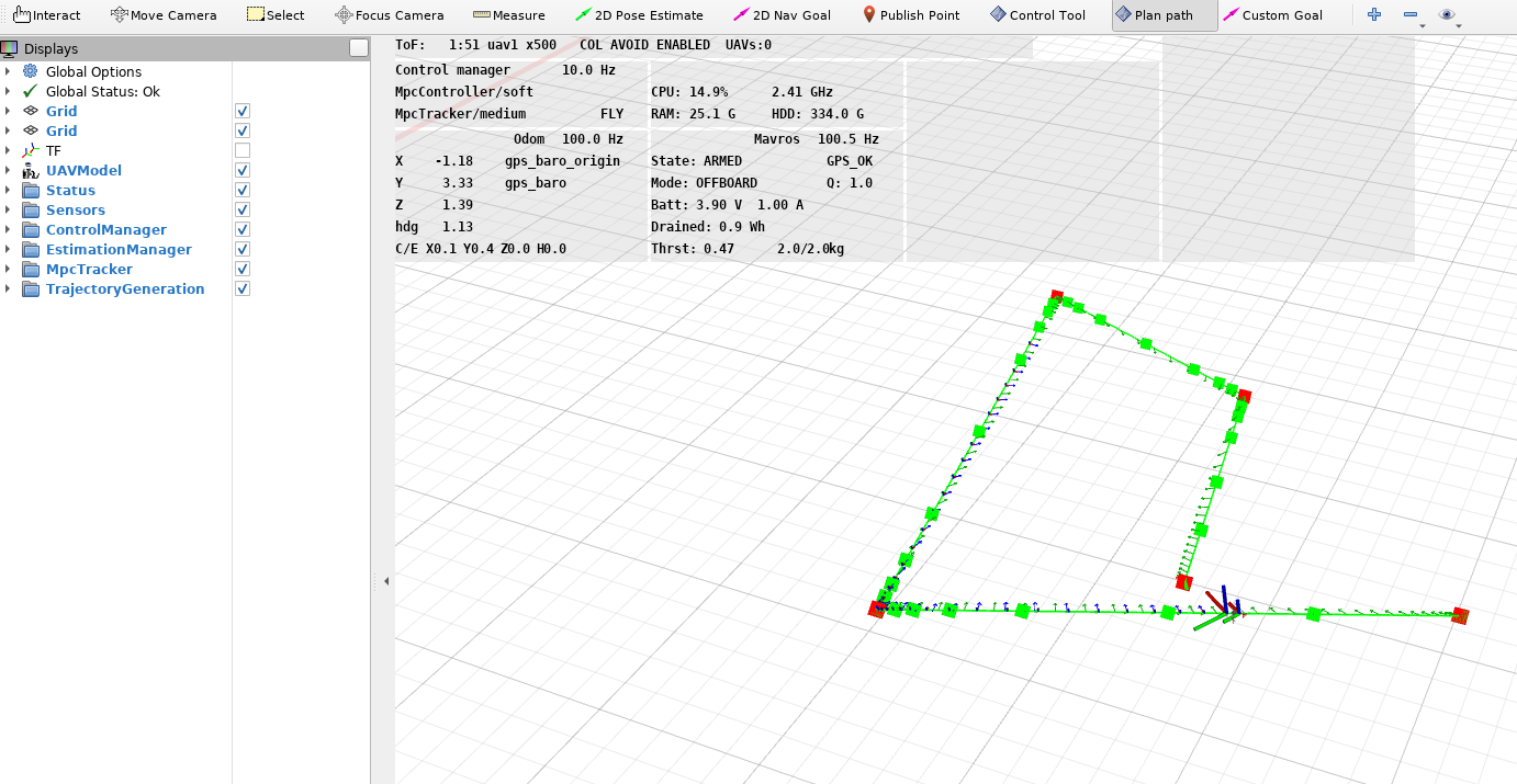
In this section, you will run your own simulation by modifying pre existing examples. The scenario we consider here is that the drone should take-off and then follow a simple square path before landing. There are different ways to do that. For example, you could use the status tab during the simulation, press "g" and input the coordinates that you want the drone to reach. Another way would be to use the Rviz window and press the "2D Nav Goal" button and set where you want the drone to go. In Rviz you can also plan a path by clicking on the "Plan path" button and set several positions and headings on the map and then press enter to start tracking the resulting trajectory (see picture).
Although these methods can come very handy, they lack autonomy as the user should set the different positions online and might lack precision depending on the tool used.
In this section, you will learn how to prepare your own tmux session that will already include the different parts for trajectory generation and tracking. You will also see how to modify the world_config.yaml file which is responsible for setting the safety area and the reference frame in which the points are expressed. This will be very important for the real world deployment.
Copy an Existing Simulation Directory
We will use the basic gazebo simulation example to create this new scenario. Open a terminal and run the following commands.
Clone the Github repository for our gazebo simulations
git clone https://github.com/ctu-mrs/mrs_uav_gazebo_simulation.git
Go to the tmux folder and copy the one_drone directory to create a new one
cd mrs_uav_gazebo_simulation/tmux
cp -R one_drone/ one_drone_trajectory_tracking/
Edit the Config File
In this new directory, we will first modify the world_config.yaml file. In this file, we will modify the frame of reference and the safety area. Find more information about the frame of references here. You can use any editor but we will use Vim in our case.
cd one_drone_trajectory_tracking/
vim config/world_config.yaml
In this file, replace frame_name by "local_origin". Doing so, the points will be expressed with regards to the starting point of the UAV. We also want to reduce the safety area to a reasonable size. We can mmodify "points" to from, for example, a 10 x 10 x 5 cube.
frame_name: "local_origin"

points: [
      -5, -5,
      5,  -5,
      5,  5,
      -5, 5,
     ]

frame_name: "local_origin"

max_z: 5
Feel free to check the other configuration files. You can override all configurations using the custom_config.yaml file. Read more about it here.
Include the Path File
In our framework, we use a ROS service to generate a trajectory based on some input points. This service takes as input a custom message that you can see by typing the following command
rosmsg show mrs_msgs/Path
While calling this service during the simulation is possible, it can be tricky to properly respect the indentation in the terminal when using multiple points. To overcome this, we can prepare a file that will call the service with the desired path. Download this file and add it to the config folder of your tmux directory one_drone_trajectory_tracking/config/. Make it executable.
chmod +x config/square_path.sh
Open this file and make sure to understand the different elements. You can find more information in the official repository. As you can see, the positions and headings of the points are listed at the bottom of the file. In the current configuration, the drone should follow a square trajectory starting from the first point specified here. Another important parameter in the message is the "fly_now", if set to true, the drone will start following the trajectory instantaneously. If set to false, another service has to be called to start the trajectory tracking.
In the points coordinates, z is set to 0 as the current altitude of the drone when the service is called is the reference one.
Feel free to test different points and settings but remember that the drone might not complete its motion if the trajectory violates the safety area.
Edit the Session File
As we discussed earlier, the session.yml file handles all the different nodes running during the simulation (and in real world). In our case, we want to add a new tab to our main window that will handle this trajectory generation and tracking. A good practice is to pre-write the desired commands we want to run and save it into the command history. You can see an example in the "goto" tab of the session.yml file.
In our case we want to put to put three separated commands in the history:
- Run the
square_path.sh - Call service to start trajectory tracking
- Land the drone with the land service
The trajectory tab should hence look like this:
- trajectory:
     panes:
       - 'history -s rosservice call /$UAV_NAME/uav_manager/land;
          history -s rosservice call /$UAV_NAME/control_manager/start_trajectory_tracking;
          history -s ./config/square_path.sh'
You can download the full session.yml file here and replace the current one.
Run the Simulation
You are now ready to run the simulation. In the one_drone_trajectory_tracking repository, run the start.sh file. If everything is working you should see the main window with the new trajectory tab, Gazebo and Rviz.
Navigate to the trajectory tab using SHIFT button + left/right arrow button. As we saved the commands in the history you should find them by just pressing the top arrow button of your keyboard.
First run the command with the square_path.sh file, you should see the trajectory being plotted in Rviz. If you get an error message try to run it again.
Then run the ROS service to start the trajectory tracking.
When the motion is completed, run the last ROS service call to land the drone.
When you want to close all windows and kill all ROS nodes running you can use the binding CTRL button + A and then K buttons and confirm with the "9" button.