UVDAR System and Simulation
This page introduces the UVDAR system and guides you through various simulations to help you understand how it works and explore its potential applications.
Introduction
Based on the MRS system and ROS, UVDAR uses blinking UV LEDs and cameras as a localization method. Each LED has a unique blinking sequence, allowing it to be identified. Using heuristics, a computing module and a Kalman filter, the system estimates the position and orientation of the detected drone within the reference frame of the observing drone.
For more information, please read :
- Fast Mutual Relative Localization of UAVs using Ultraviolet LED Markers
- Mutual Localization of UAVs based on Blinking Ultraviolet Markers and 3D Time-Position Hough Transform
- UVDAR System for Visual Relative Localization with Application to Leader-Follower Formations of Multirotor UAVs
Installation
If the MRS system is not yet installed on your laptop, please refer to and complete the instructions on this page first.
Then, to use the UVDAR system, you can proceed with a native installation:
sudo apt install ros-noetic-uvdar-core
sudo apt install ros-noetic-uvdar-gazebo-plugin
Or, clone the repositories from GitHub into your local Git repository:
git clone https://github.com/ctu-mrs/uvdar_core.git
git clone https://github.com/ctu-mrs/uvdar_gazebo_plugin.git
First Simulation
To launch your first simulation, execute the following command:
roscd uvdar_core/scripts/two_drones
Next, open the start.sh file with your editor (e.g., nano, vim) and check the shebang line to ensure it matches the shell the interpreter you are using. By default, it is set to Z shell (zsh), so if you are using Bash, change #!bin/zsh to #!bin/bash. Save your changes and close the file.
You can then execute the start.sh file :
./start.sh
Normally, three windows should open: Gazebo, Rviz, and Ocv_uvdar_blink_uav1.
If the last window doesn’t appear, try re-running the command line in the "uv_observer" window. If the problem persists, stop the simulation and navigate to the launch directory (~/opt/ros/noetic/share/uvdar_core/launch). Open the sim_three_sided.launch file with a text editor.
For example :
sudo chmod a+w sim_three_sided.launch
vim sim_three_sided.launch.
Next, increase the sleep parameter on line 121; its original value is 10, so change it to 15. Do the same for line 156, where the original value is 15, and increase it to 25. If the issue persists, continue to gradually increase these values. If it still doesn’t resolve the issue, it might be due to another problem. However, keep in mind that this will not affect the rest of the simulation. While the simulated camera images may not appear, the positions will still be calculated correctly.
In the Gazebo window, you should see two drones facing each other and taking off. If the simulation seems very slow, that’s normal, it has been slowed down.
You can see this in the slow_down tab, where the command gz physics -u 80 has been executed.
If you want, you can switch to real-time simulation with the command gz physics -u 250, but the pose node calculator might struggle to handle all computations, and you may see many error messages in the uv_observer tab saying "No Hypotheses provided. Returning!".
In the Rviz window, you should see a 2D grid, with UAV 1 represented as a point in the center of the grid, and UAV 2 as a point positioned at its estimated location within the frame of UAV 1.
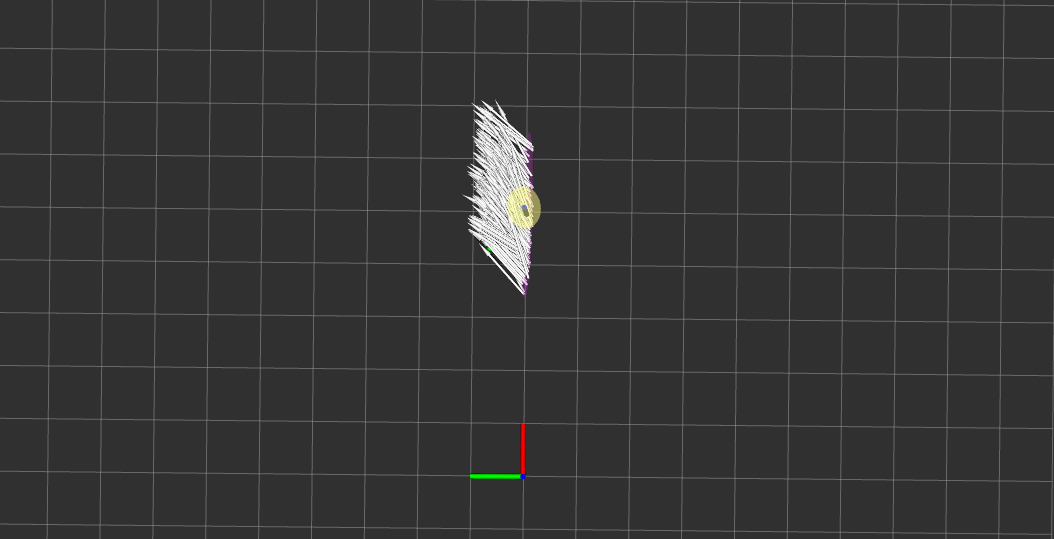
In the Rviz display window, you will see a topic called “Hypotheses”. You can uncheck this option, causing the white arrows to disappear and providing a clearer view.
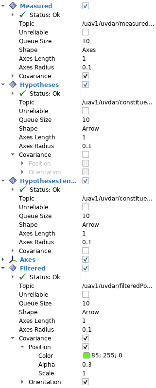
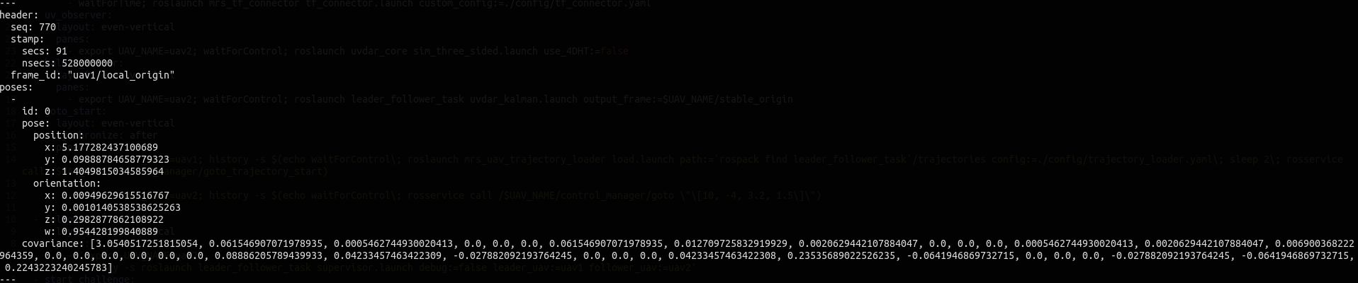
Another topic in the display window is called “Measured”, which represents the /uav1/uvdar/measuredPoses rostopic. It is displayed as a set of axes and two ellipsoids: a purple one for the position and a green one for the orientation of the drone. The purple ellipsoid is stretched longitudinally because the distance from UAV 1 to UAV 2 is the least precise measurement. You can view the mean of the measured position by executing, in another terminal, the following command:
rostopic echo /uav1/uvdar/measuredPoses.
Or, a filtered version:
rostopic echo /uav1/uvdar/filteredPoses
You will notice that the orientation is represented by four variables: x, y, z, and w, which correspond to a quaternion.
In the Ocv_uvdar_blink_uav1 window, you should see three screens corresponding to the fields of view (FOV) of the three cameras: right, left, and back, covering a full 360° around the drone. The drones are localized on the screen, usually indicated by two or three colored circles with an ID displayed at the top of each, depending on their orientation. These represent the perceived LEDs. If you see the drones on two screens, that’s normal, as there is some overlap. To observe how the perceived UAV is tracked, you can navigate to the status tab and enable remote mode for UAV 2.

Run Your Own Simulation
First Example
From now on, it is recommended to work with clones of the GitHub repositories and create your own branch for development. This approach allows you to make changes independently without impacting the main repository.
We can easily integrate the work done in the simulation tutorial page with what we have now. We will create a two_drones_in_motion repository to simulate a scenario where UAV 2 moves while UAV 1 tracks its position. First, make a copy of the "two_drones" repository :
sudo cp -r /your_path/scripts/two_drones /your_path/scripts/two_drones_in_motion
Replace "your_path" with the path to your cloned "uvdar_core" repository (or use /opt/ros/noetic/share/uvdar_core if you are still using the native installation).
Now, let's reuse the square_path.sh file :
sudo cp ~/your_path_to_mrs_uav_gazebo_simulation_repository/tmux/one_drone_trajectory_tracking/config/square_path.sh /your_path/scripts/two_drones_in_motion/config
Next, in the "two_drones_in_motion" repository, edit the session.yml file using your editor. For example :
vim session.yml
And add the following section:
- trajectory
    layout : tiled
    panes :
    -  export UAV_NAME=uav2 ;
        history -s rosservice call “ /$UAV_NAME/uav_manager/land“ ;
        history -s rosservice call “ /$UAV_NAME/uav_manager/start_trajectory_tracking“ ;
        history -s ./config/square_path.sh
Finally, in the two_drones_in_motion repository, execute the start.sh file. Wait for everything to launch successfully and for the drones to take off. In the trajectory tab, press the up arrow key on your keyboard and execute the command line stored in memory. You will see UAV 2 moving within UAV 1's camera view, using the UVDAR pose calculation for tracking.
Seconde Example
Now, let’s explore the potential of the UVDAR system with a more complex task. We will implement a leader-follower behavior using the localization data provided by UVDAR. This setup will enable UAV 2 to autonomously follow the movements of UAV 1.
First read the documentation and clone this GitHub repository into a catkin workspace (for more information about catkin workspaces, refer to the ROS tutorials).Then, switch to the "three_sided" branch.
git switch three_sided
In this branch, the main change is the session.yml file: for the "uv_observer" window, we modify the command from roslaunch leader_follower_task uvdar_dual_cameras.launch to roslaunch uvdar_core sim_three_sided.launch.
This update enables the follower drone to achieve a full 360-degree field of view (FOV).
Once your workspace is built with catkin you can run a first leader-follower task simulation:
cd /path_to_your_worspace/src/leader_follower_task/tmux_scripts/simulation_two_drones
./start.sh
Wait for all windows to launch (Gazebo, Rviz, Ocv_uvdar_blink_uav2). The camera window may take some time to appear; if it doesn't open, refer to the First simulation section for troubleshooting.
In the "goto_start" tab, press the up arrow key on your keyboard and hit Enter to load the leader's trajectory (which should be a circle), positioning both drones at their starting locations (the follower's starting position can be modified in the session.yml file).
Next, switch to the "follower" tab and execute the command stored in memory, just as you did in the "goto_start" tab. This will launch the supervisor node, allowing the follower drone to move according to the behavior defined in the follower script. Finally, switch to the "start_challenge" tab and execute the command in memory. You will see the leader drone begin following its trajectory, with UAV 2 following it.
Once the leader has completed its trajectory, you can stop the simulation by pressing Ctrl+A followed by K and confirm with 9.
Experiment On Your Own
Now, feel free to experiment by modifying the follower.cpp file to create your own custom follower control commands. Keep in mind that everything here is in the world frame.This applies to all data that is received by the follower as well as the calculated reference point, trajectory or velocity.
Don't forget to run catkin build in your workspace to recompile the follower.cpp file every time you make adjustments. This ensures that your changes are applied in the simulation.
You can also modify the leader's trajectory by editing the trajectory_loader.yaml file in the "config" repository and setting the trajectory name to one of the options available in the trajectory repository.
Moreover, you can switch to the "three_sided_fcu_control" branch of the repository and experiment by receiving UVDAR data directly in the follower's fcu (flight control unit) frame and sending control actions within this frame.
git switch three_sided_fcu_control
The follower.cpp file already contains an example of reference point control, inspired by the ideas discussed in this article : UVDAR System for Visual Relative Localization with Application to Leader-Follower Formations of Multirotor UAVs. Feel free to read it for further insights.